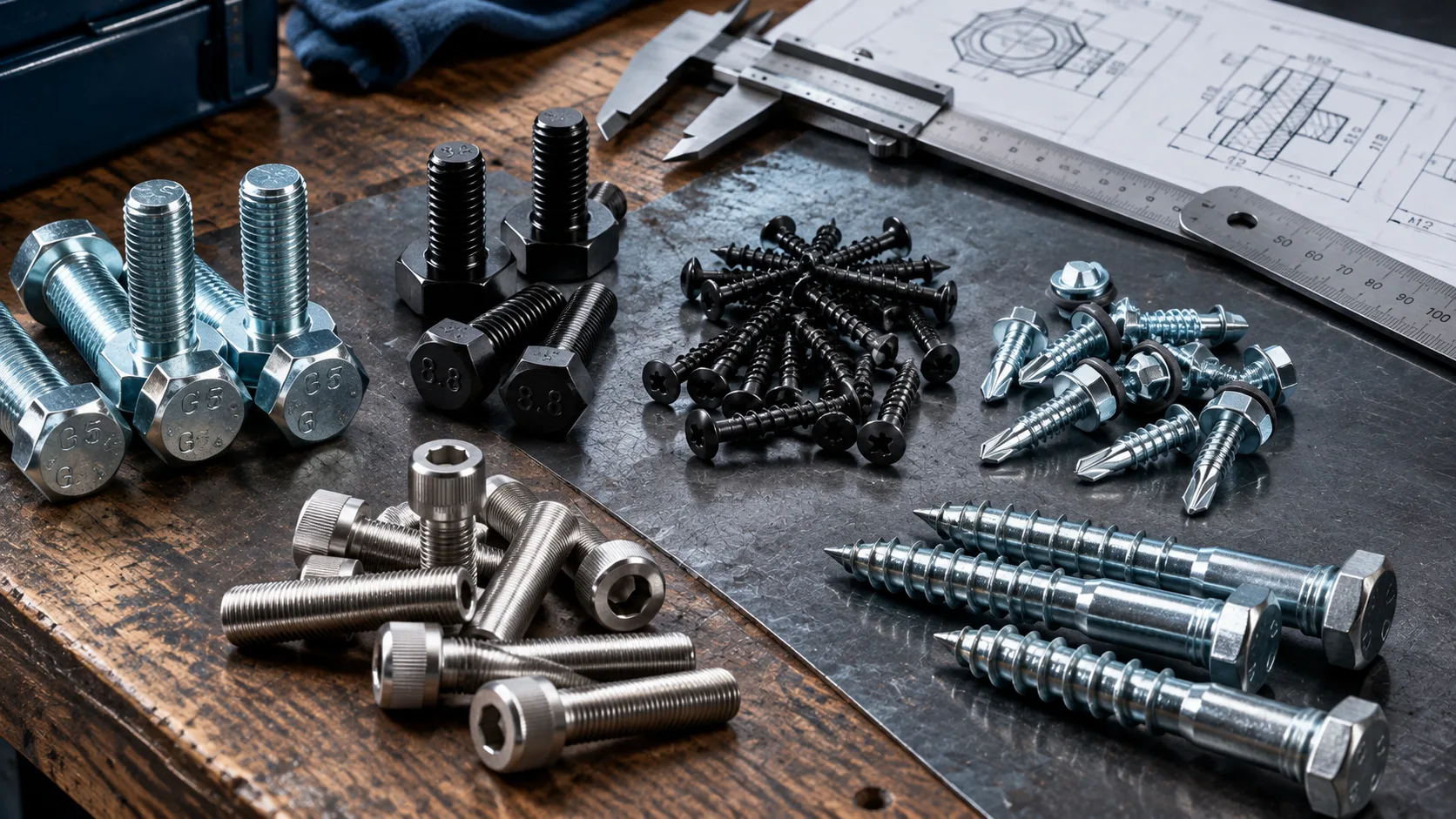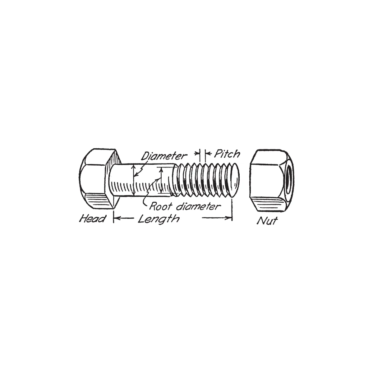
Mechanically, a screw functions as an engineering transducer that converts applied rotational torque at the head into an axial tensile preload clamp along its axis via the physical principle of the helical inclined plane. Its four anatomical regions —head, unthreaded shank (grip length), threaded length, and point— dictate tensile yield capacity, shear strength, and dynamic vibration resistance.
While a screw appears to be a modest metal fastener on the hardware shelf, its dimensions adhere to stringent metrological standards. Understanding fastener anatomy prevents costly workshop errors, eliminates vibrational loosening, and ensures structural assemblies withstand design loads without yielding.
General Architecture of an Industrial Screw
Every industrial mechanical fastener consists of four distinct functional sections:
               === HEAD (Bearing surface and drive recess)
               | |
               | | UNTHREADED SHANK / GRIP (Solid smooth section)
               | |                                       } SHANK / BODY
               |s|                                       }
               |s| THREADED LENGTH (Helical crests & root)
               \ /
                V  POINT (Pilot entry or self-drilling tip)
1. The Head: Drive Engagement and Clamping Interface
Located at the top end of the fastener, the head performs two critical mechanical tasks:
- Drive Recess / Drive Feature: The geometric recess or external profile (hex, Phillips, socket head Allen, or Torx) that mates with the driving tool to transmit tightening torque.
- Bearing Surface (Underhead area): Acts as a mechanical stop to limit penetration and distribute axial clamping pressure across the joint interface or washer.
Technical reference: For torque capabilities and recess geometries, refer to our comprehensive guide on Classification of Screw Heads and Drives.
2. The Shank (or Fastener Body)
The cylindrical shaft that penetrates mating components. In engineered fasteners, the shank is divided into two functional zones:
A. The Unthreaded Shank or Grip Length
The solid, smooth portion of the shank. Including an unthreaded shank is a deliberate engineering design requirement:
- Prevention of "double threading" (cross-binding): When joining two members (such as timber framing or steel brackets), if threads engage both pieces simultaneously, the pieces bind and cannot pull tight against one another. The smooth shank allows the top member to slide freely while the threads pull the base member, creating a tight clamp.
- Superior Shear Resistance: The smooth shank retains full nominal diameter without thread valleys that serve as stress risers, providing far greater resistance against transverse shear loads.
B. The Threaded Length
The portion where helical ridges are rolled or machined:
- Full-thread screws (DIN 933 / ISO 4017): Threads extend entirely to the bearing surface; ideal for thin sheet metal, tapped blind holes, and compact through-bolted joints.
- Partial-thread bolts (DIN 931 / ISO 4014): Combines an unthreaded grip with standardized thread length; specified for joints subject to cyclic bending and transverse shear.
3. The Thread: Mechanics of the Clamping Helix
The thread profile transforms angular rotation into linear clamp load. Fastener metrology defines four fundamental features:
- Thread Ridge: The continuous helical protrusion that engages mating threads or displaces base material.
- Crest: The outermost peak of the thread profile, defining the major nominal diameter (e.g., 8 mm on an M8 fastener).
- Root: The bottom of the groove between adjacent threads, defining the minor (core) diameter that bears tensile proof loads.
- Flank: The angled sides connecting the crest and root, transferring bearing contact forces and friction under preload.
Fastener Anatomy and Mechanical Functions Matrix
| Fastener Zone | Measurement Parameter | Mechanical Function | Standard Specification |
|---|---|---|---|
| Head | Bearing diameter & head height | Torque transmission & clamp distribution | ISO 4759-1 / DIN 931 |
| Unthreaded Shank | Full nominal diameter (d) | Shear resistance with zero stress notch effect | DIN 931 / ISO 4014 |
| Thread Crest | Major nominal diameter | Dimensional classification & pilot alignment | ISO 68-1 / ASME B1.1 |
| Thread Root | Minor (core) tensile diameter | Tensile stress area resisting axial fracture | ISO 898-1 |
| Thread Flank | Flank angle: 60° (Metric/UNC) or 55° (Whitworth) | Load transfer interface and frictional locking | ISO 261 / BS 84 |
| Point | Gimlet, TEK drill (DIN 7504), or flat chamfer | Material displacement, metal drilling, or guided lead-in | DIN 7504 / ISO 1478 |
Thread Pitch: Metrology and Operating Principles
Thread pitch defines the axial advancement achieved per single 360-degree rotation of the fastener:
- ISO Metric System: Measured directly in millimeters from crest to adjacent crest (e.g., M10 × 1.5 denotes 1.5 mm axial distance between threads).
- Imperial Unified System (UNC/UNF): Determined by the count of Threads Per Inch (TPI). For instance, 3/8"-16 UNC carries 16 threads per linear inch.
Engineering Rule of Thumb:
Coarse pitch threads drive quickly and tolerate dirty or soft materials. Fine pitch threads provide higher tensile stress area and significantly superior resistance against vibrational loosening under cyclical operational loads.
4. The Point: Lead-in Geometry
- Gimlet (sharp tapered) point: Displaces and compresses wood grain or expands nylon wall plugs.
- Self-drilling point (DIN 7504): Features cutting flutes that drill pilot holes in steel and tap mating threads in a single pass.
- Flat chamfered point: Standard on machine bolts; guides insertion into tapped holes or nuts without cross-threading.
Technical Metrology Support at Bulonera Alvear
At Bulonera Alvear, our technical counter is equipped with metrological measurement tooling (digital vernier calipers and standardized thread pitch gauges) to accurately verify Metric, Unified, and Whitworth fasteners. Bring your sample for identification.
📍 Av. Alvear 1301, Resistencia, Chaco, Argentina. Regional logistics network and coordinated shipping options nationwide.
Frequently Asked Questions: Screw Anatomy
How is the length of countersunk flat head screws measured compared to hex head bolts?
Screws with protruding heads (hex, pan, socket head) are measured from underneath the bearing face to the point. Countersunk flat head screws are measured overall including head thickness, as the entire fastener embeds flush.
What is nominal diameter versus minor core diameter?
Nominal diameter is measured across thread crests (e.g., 6 mm for an M6 screw). Minor core diameter is measured across thread roots and represents the solid net section resisting tensile fracture.
Why does a screw with an unthreaded shank offer higher shear capacity?
Because the unthreaded shank maintains 100% of solid steel cross-section, eliminating thread valleys that act as mechanical stress concentration points under lateral shear loads.
Related Guides in This Series
- Screw Types Guide: Technical Classification and Selection (Pillar Page).
- Classification by Head Style and Drive Types (Next installment).
Bulonera Alvear — Building the future, bolt by bolt!